Have you ever found yourself frustrated with a seemingly dead battery, only to wish you could squeeze just a bit more energy out of it? Perhaps you've been in a situation where you needed a light source but didn't have fresh batteries on hand. If so, you're not alone. Many of us have faced similar dilemmas, but fear not - there's a solution that's both practical and surprisingly simple: the Joule Thief circuit.
The Joule Thief circuit is a clever little device that can extend the life of a battery by allowing you to power an LED even when the battery's voltage has dropped to as low as 0.6 volts. Essentially, it's a self-oscillating boost converter that requires just a few basic components: a transistor, a resistor, and a homemade transformer. This circuit has gained popularity among electronics enthusiasts for its ability to extract the last drops of energy from seemingly depleted batteries.The Problem: Maximizing Battery Life
Picture this: you have a flashlight powered by a single AA battery. Over time, as the battery drains, the light becomes dimmer until it eventually seems to die out completely. But what if there was a way to keep that light shining just a little bit longer, even when the battery's voltage is well below its nominal level?
The Solution: Enter the Joule Thief
The Joule Thief circuit provides exactly that solution. By cleverly manipulating the voltage and current from the battery, it can continue to power an LED even when conventional circuits would fail. The circuit operates by rapidly switching the current through a homemade transformer, creating pulses of energy that are then used to drive the LED.
How It Works
The circuit itself is relatively simple. It consists of a transistor, a resistor, and a homemade transformer. The transformer is typically made by winding a few turns of enameled copper wire around a small ferrite core. The number of turns and the size of the core can vary depending on the specific requirements of the circuit.
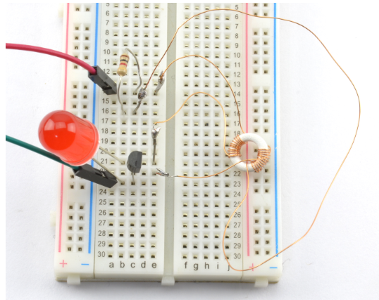
Shown below is the DIY Joule Thief Circuit diagram for powering a battery.
I personally made my transformer by winding 12 turns of 30 AWG (34 SWG) enameled copper wire around a tiny toroidal ferrite core. However, experimentation is encouraged, and different combinations of wire gauge, core size, and number of turns can yield interesting results.
Practical Experience: Building Your Own Joule Thief
Building a Joule Thief circuit is a rewarding experience that requires only basic soldering skills and a handful of inexpensive components. Here's a basic rundown of how to build one:
Gather Your Components: You'll need a transistor (such as a 2N3904), a resistor (around 1 kΩ), some enameled copper wire, a small ferrite core, and an LED.
Wind Your Transformer: Wind a few turns of wire around the ferrite core to create your transformer. Experiment with different numbers of turns to achieve the desired performance.
Assemble the Circuit: Connect the components according to the schematic diagram, making sure to pay attention to polarity and component orientation.
Test and Adjust: Once assembled, power up the circuit with a depleted battery and observe the LED. If everything is working correctly, the LED should light up, even with a low battery voltage.
Experiment: Don't be afraid to experiment with different component values and configurations. You may discover new ways to optimize the circuit for your specific needs.
Conclusion
In conclusion, the Joule Thief circuit is a simple yet ingenious solution for extending the life of batteries and powering LEDs with minimal voltage. By harnessing the power of self-oscillation and transformer action, this circuit demonstrates the beauty of practical electronics. So why not give it a try? With just a few basic components and a bit of experimentation, you can unlock the hidden potential of seemingly dead batteries and keep your battery powered projects like the ones illustrated previously autonomous robot with arduino or wifi controlled robotic car powered up for longer.
See also, How to Make a DIY LiPo Charger and How to estimate Battery life?


