In this tutorial, we'll delve into the basics of using a push button to control an LED on an Arduino board. Push buttons, also known as momentary contact switches, are essential components in many electronic projects. We'll explore how to wire up a simple circuit on a breadboard, debounce the button for reliable performance, and write the necessary code to control an LED based on the button's state.

Understanding Push Buttons
Push buttons typically come in two types: normally open and normally closed. For our purposes, we'll focus on normally open switches, which are more common. These switches complete a circuit when pressed and then break it when released.
It's essential to note that the tactile switches often used for breadboarding have four legs, not two as one might expect. The two legs on each side of the switch are internally connected, meaning there are only two distinct wires. Figure below illustrates two switches, showcasing this internal connection.


Debouncing the Button
In Figure below, you'll notice a 10kΩ resistor connected in parallel with the push button. This setup serves to debounce the button, ensuring reliable operation. Without this resistor, the pin connected to the button may float when the switch is unpressed, leading to erratic behavior in our code.

Hardware Setup
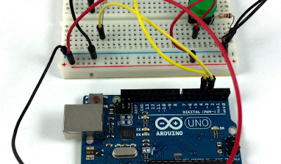
After following the wiring instructions, your breadboard setup should resemble Figure below. Now, let's move on to writing the corresponding software.
Writing the Code
Open a new sketch in the Arduino IDE and paste the following code:
#define LED_PIN 3
#define BUTTON_PIN 4

int val;

void setup() {
  pinMode(LED_PIN, OUTPUT);
  pinMode(BUTTON_PIN, INPUT);
}

void loop() {
  val = digitalRead(BUTTON_PIN);
  if (val == HIGH) {
    digitalWrite(LED_PIN, HIGH);
  }
  if (val == LOW) {
    digitalWrite(LED_PIN, LOW);
  }
}
In this code snippet:
- We define the pins for the LED and the push button.
- In the setup function, we set the LED pin as OUTPUT and the button pin as INPUT.
- The loop function continuously checks the state of the button pin. If it's HIGH (button pressed), the LED turns on; if it's LOW (button released), the LED turns off.
Uploading the Sketch
Save the sketch file and verify it by clicking the appropriate buttons in the Arduino IDE. If successful, proceed to upload it to your Arduino board. You should observe the RX and TX LEDs lighting up during the transfer process.
Testing the Setup
Once the upload is complete, push the button. The LED should illuminate while the button is pressed and turn off when released.
Congratulations! You've successfully created a basic Arduino circuit that controls an LED using a push button. Feel free to experiment further and integrate additional functionalities into your projects. Happy tinkering!