Here it shown how to write program ATmega328p microcontroller USART and illustrate how USART works by showing example of communication between ATmega328p and PC. The USART is configured to send message to the PC. On the PC using terminal we can observe whether the message sent by the microcontroller is received or not. This confirms whether the ATmega328p and PC communicates successfully or not. It is necessary to learn how microcontroller USART works because is needed whenever the microcontroller needs to communicate with other devices such as bluetooth modules, another micrcontroller, GSM module, wifi module etc
Watch the following video to know what to expect in this tutorial.
To follow this tutorial example you will need the following components.
- ATmega328p
- 11.0592MHz crystal oscillator
- 10KOhm resistor
- Two 22pF capacitors
- Push button
- 5V regulated power supply
- AVR ISP MK2 programming tool(or any other programming tool)
- USB to TTL converter
- Wires
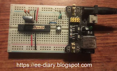
Below picture shows the ATmega328p along with 10KOhm pull-up resistor, the 11.0592MHz oscillator, the 22pF capacitors and the reset button.

The picture below shows the connection between ATmega328p, AVR ISP MK2 and USB to TTL converter which is connected to the PC.
The schematic diagram below shows the connection required.
The C program code for sending string message from ATmega328p microcontroller USART to the PC is provided below:
#ifndef F_CPU
#define F_CPU 11059200UL
#endif

#include <avr/io.h>
#include <util/delay.h>


#define UBRRVAL 71 //9600 baud rate for 11.0592 MHz CPU frequency

void usart_init(void);
void sendbyte(unsigned char);
void sendstr(unsigned char *);

unsigned char msg[] = "Hello from ATmega328p!\n";

int main(){

    usart_init();

   while (1){
	sendstr(msg);
	_delay_ms(1000);
      }

   return 0;
 }

void usart_init(void){
    //Set baud rate
	UBRR0H= (unsigned char)(UBRRVAL>>8);   //high byte
    UBRR0L=(unsigned char)UBRRVAL;     			//low byte
	//Enable Transmitter and Receiver and Interrupt on receive complete
    UCSR0B |= (1<<TXEN0);
    //Set data frame format: asynchronous mode,no parity, 1 stop bit, 8 bit size
    UCSR0C |= (1<<UCSZ01)|(1<<UCSZ00);

}

void sendbyte(unsigned char MSG){
    while((UCSR0A&(1<<UDRE0)) == 0);
    UDR0 = MSG;
}

void sendstr(unsigned char *s){
	unsigned char i = 0;
	while(s[i] != '\0'){
	 sendbyte(s[i]);
	 i++;
	 }
}
In the program we have defined our CPU frequency as 11.0592MHz using the F_CPU statement. We made the the usart_init() function to configure the microcontroller USART by doing the followings:
- loading the UBRR register with value of 71 for 9600 baud rate for frequency of 11.0592MHz(see datasheet)
- turn on the transmitter by setting the TXEN bit in the UCSR0B
- configured the microntroller in asynchronous mode with 8 bit data and 1 stop bit by by seeting the UCSZ01 and UCSZ00 bits in the UCSR0C.
We created the sendbyte() function wherein we check whether the transmit buffer is empty or not by periodically checking the UDRE0 flag in the USCR0A register. If it UDR0 register is empty then we load the data into the UDR0 register that is sent to the sendbyte() function as parameter.
We also created sendstr() function to send strings. This function accepts strings as pointer to the character array of the message which is defined at the top outside the main() function msg[]="Hello from ATmega328p!\n". Using the sendbyte() function we send each character in the array until the \0 is reached.
In the while() loop we can the sendstr() to send our message. We have used _delay_ms() function to create a delay of 1 second between each string sent.
Here we have used Atmel studio 7 for programming and uploading the hex file. If you don't know how to use Atmel studio for programming and uploading code see our earlier tutorial How to Program ATmega328p using ATMEL Studio & AVR ISP MKII.
You basically start by creating a new GCC C Executable project. Provide some name for the project and save the project in some directory on your computer. Example is shown below.
In the device selection window select ATmega328p as your device.
In the project, a default main.c will open in the code editor. Write the C program for USART communication provided above. After that select the Release option then build the solution. You should not get any build errors.
Open the device programming and then select the AVRISP MK2, ATmega328p as device, click on the Read button under the Device signature. If everything is ok here the microcontroller is ready to be programmed.
From the Memories option, browse to the Release folder inside your project folder and select the hex file you created earlier during the build process. The click on the Program button.
If everything is ok, the program will be uploaded to the ATmega328p chip. You should connect the USB to TTL converter if you have not done so.
Then open the Tera Term(or any other terminal if you have) and select Serial with the Port to which you USB to TTL converter is connected to.
Now we have to set up the serial com port. Go to and open the Serial Port setting from the Setup > Serial port as shown.
From the setup window, make the Speed to 9600, Data to 8 bit, Parity None, Stop bits to 1 bit Flow control none as shown below.
Then you should the message "Hello from Atmega328p!" as sent by the ATmega328p on the tera term window.
If you don't have tera term you can also use the Arduino IDE serial monitor. Make sure that the COM port to which the USB to TTL converter is connected on your PC is free(available). Also as in tera term, you have to set the correct baud rate which is 9600.
So in this tutorial we showed how to write program to communicate ATmega328p with PC using the UART of the microcontroller. Another atmega328p uart example is communication between two AVR microcontrollers.


